Design of Magnetic Level Gauge
2019-06-17
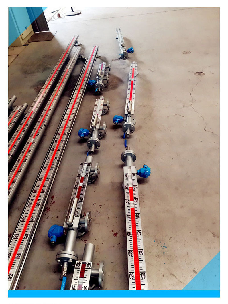
The magnetic level gauge consists of:
· a vertical chamber consisting of a tube of suitable diameter and thickness containing a float wherein a permanent magnet is placed exactly on the liquid level line
· two horizontal stub pipes for connection to the vessel containing the liquid of which we wish to know the level
· two stop valves (recommended, but not mandatory) one on each stub pipe, to isolate the level gauge
· an indicating scale, outside the vertical chamber, consisting of a case of non-magnetic material with transparent front face containing a set of small permanent magnets enclosed in small cylinders which can rotate on their horizontal axis.
These cylinders show an external surface having two different colours.

The indicating scale will be of one colour (e.g. white) over the chamber area taken up by gas, vapour or steam phase contrasting with the other colour (e.g. red) over the chamber area taken up by liquid phase.
Alarm system for damaged float. The three bottom cylinders of the indicating scale are placed lower than the bottom connection of the magnetic level gauge. They are used for control of float efficiency. With float damaged and its consequent sinking in the liquid, these three cylinders show the yellow surfaces.
These level gauges are very suitable for interface reading: the level gauge float has only to sink in the liquid having lower specific gravity and to float on the liquid having higher specific gravity.


