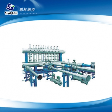
Sonic nozzle gas flow standard device (commonly known as flowmeter calibration device), the main use is used in the measurement and calibration gas transmission process gas trade settlement displacement meter or speed meter, to purify the dry air as medium, using automatic flow standard device (negative pressure method). It chooses ISO9300 conforms to the national standard "critical flow venturi nozzle measuring gas flow rate, the critical flow high nozzle as a standard flow meter, using the standard table method for flow verification or testing. In meeting to check under the premise of different types of flowmeter, the device is highlighted incorrect degree is low, wide range of degrees, high degree of automation, checked the instrument variety, novel structure, etc. Can be used in the industries of petroleum, chemical industry, city gas in the gas flow meter verification and testing, especially is suitable for the detected flowmeter variety, wide test of working face, flow meter inspection quantitative metrological verification unit, gas companies and large-scale industrial and mining enterprises, etc.
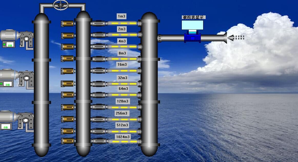
Features:
1, the nozzle structure is simple, durable, easy to copy and inspection, the uncertainty of the outflow coefficient ≦ 0.2 ﹪
2, the device has the advantages of compact structure, good repeatability and reliability.
3, at work, can free combination multiple nozzle according to the volume of traffic, so wide measurement range. of 1 m/h, ceiling in the following for maximum flow device.
4, high precision and differential pressure transmitter, temperature transmitter is used for the measurement data and the average method for many times, into the next step to ensure the accuracy of the collected data.
5, in the process of flow test, using advanced pulse counting pulse interpolation technology, fully guarantee the measured flow pulse preliminary.
6, the freedom to choose flowmeter calibration verification time, volume, flow verification points, etc., greatly convenient for user operation.
7, software, the operation is simple, with operating permissions, user can according to the actual situation in the configuration database content.
Sonic nozzle flow calibration device selection is often more than parallel sonic nozzle flow. Device on negative pressure method, from the interior of the atmospheric air into the pipe straight before experiment, through the detected flowmeter into stagnation after container, the sonic nozzle to return to the atmosphere. Through measured before and after the instrument of basic parameters such as PT and PT at the entrance of the nozzle, can calculate the flow or basic error or meter coefficient. Sonic nozzle is essentially a transfer standard, under ideal conditions, by the speed of sound into the quality of the nozzle flow is:
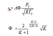
Type of nozzle throat area A is the speed of sound; ф is critical flow under the condition of ideal functions; P0, T0's stagnation pressure before the sonic nozzle and stagnation temperature; R is the gas constant, the air, industry preferable 287.1 J/(kg · K).Sonic nozzle flow rate formula of the actual conditions should be to modify qm in outflow coefficient C, it is on the one dimensional isentropic flow assumptions, usually in the original gas flow standard device (such as PVTt, Mt method, etc.) on the actual calibration. Practice shows that it is a function of Reynolds number, generally can be represented as:

Compared with other standard flowmeter, sonic nozzle has the following advantages:
Working principle of the 1) clear, traffic can be a empirical formula, said in the original standard device calibration of outflow coefficient C under different operating conditions can be applied to the application;
2) has the very good repeatability;
3) is not affected by upstream velocity distribution of the nozzle, so straight pipe upstream do not need to be very strict requirements;
4) only depends on the upstream of the flow fluid parameters, and a linear relationship with mass flow rate and inlet stagnation pressure, do not need to measure static pressure in the velocity change dramatically. In critical flow condition, the impact of the change from the downstream pressure.
5) to adapt to the wide range of temperature, pressure, flow range is high, the structure is compact, price moderate.
Control system is composed of controller (work station) and personal computer, installed in the control cabinet (work station) within the special instrument and data acquisition unit, data acquisition and control. Personal computer is used to state observation, data processing, data storage, printing, etc, and the simulated control system.
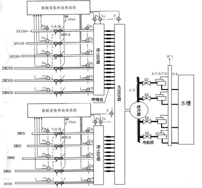
Technical parameters:
1) the maximum flow Qmax: 7000 m3 / h, flow Qmin: 1 m3 / h;
2) device, the expanded uncertainty Urel < 0.25% k = 2;
3) the working pressure of 80 ~ 103 kpa (pabs);
4) working temperature 0 ℃ ~ 45 ℃;
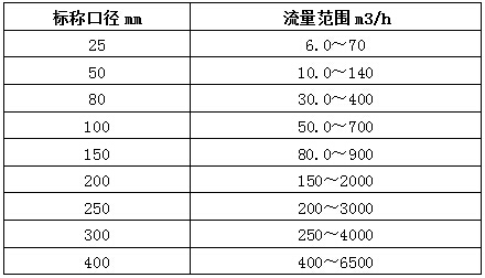
5) test pipeline configuration DN15 ~ DN400;
6) vacuum pump configuration

Device can test meter:
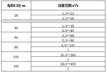
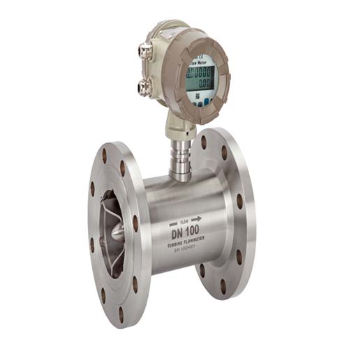
Speed meter (represented by the turbine flowmeter) :
Before the device is working, the air flow through straight pipe into the inspection instrument, through a straight pipe to stagnation after container into the nozzle, gas into the vacuum pump eventually emptying the atmosphere. Automatic sampling device microcomputer system in the process of testing temperature, pressure, the pulse signal parameters and record test time. According to the predetermined calibration program, the computer automatically choose test flow nozzle (regulation), at the completion of a flow meter calibration automatically after the original print detection data.
Other system configuration:
1) integrated temperature transmitter
Accuracy: 0.15 on the Richter scale are unlikely
Measuring range: 0 ℃, 50 ℃
Explosion-proof grade: Exd Ⅱ BT4
Installation location: measuring pipeline, stagnation containers
2) absolute pressure transmitter
Accuracy: 0.1 on the Richter scale are unlikely
Explosion-proof grade: Exd Ⅱ BT4
Location: measuring line, stagnation containers, manifold
3) precision absolute pressure gauge
Accuracy: 0.25 on the Richter scale are unlikely
Installation location: manifold vacuum pump
4) precise pressure transmitter
Accuracy: 0.25 on the Richter scale are unlikely
Installation location: cooling water pipeline
5) mercury thermometer
Dividing value: 0.1 ℃
Installation position: test line
Main technical parameters of control system:
1) input signals:
A) pulse signal waveform: square wave or sine wave
Count range: 0-4294967295 times
Technical frequency: 0.1-2 KHZ
Measurement error: N + 1 pulse number (N accumulated pulses)
B) signals: pressure: 4-20 ma (range is provided by the user)
Temperature: 4-20 ma (range provided by the user)
2) working environment:
Ambient temperature: 0-45 ℃
Environmental humidity: 35% - 35% RH, no condensation.
The atmospheric pressure: 86 kpa to 106 kpa
Dust condition: no dust
3) power supply
The power supply voltage: 380/220 vac three phase four wire
Power frequency: 50 hz plus or minus 5% power supply capacity: < 10 kva
Voltage range: 85% - 110% of the power supply voltage


